Installation Guides
Suntech Hardwire Tracker

Suntech ST4215 & 4300 Installation Guide
Installation Instructions for the Suntech ST4215 and 4300 Series Tracking Devices with the 3 wire harness
Tools required:
- Wire crimper
- Digital multi-meter
- Phillips screwdriver
- Self-tapping sheet metal screws (#8 x 1/2″ recommended)
- Flat head screwdriver or trim removal tool
- Electrical tape
- Zip ties.
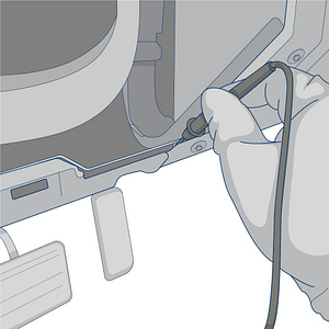
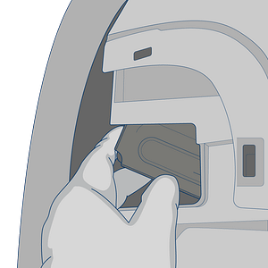
Use a flathead screwdriver or trim removal tool to remove the panel from the lower portion of your driver’s side dashboard
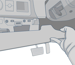
Once removed, set the panel aside to see the exposed portion underneath your dashboard.
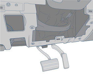
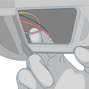
Locate the vehicle’s constant & ignition power wires in the steering column, at the fuse block, or Body Control Module.
Setup your digital multi-meter and set to 20v in the DCV section.
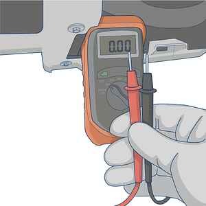
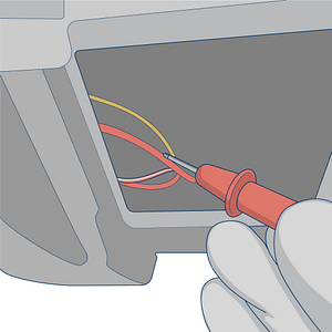
Connect the black ground wire from the multi-meter to a metal portion of the framing under the dashboard.
Locate the wire that you suspect would be the constant power wire. Probe the wire with the red multi-meter lead. Turn the vehicle’s ignition ON and OFF while the red meter lead is connected. If the meter shows 12volts when the ignition is BOTH ON and OFF, then it is the constant wire.
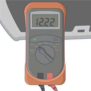
Locate the wire that you suspect to have switched (ignition) power. Probe the wire with the red multi-meter lead. Turn the vehicle’s ignition ON (without fully cranking to a start). The multi-meter should display greater than 12 volts while in this ignition position.
With the red multi-meter lead still probing the ignition wire, turn the vehicle’s ignition ON to a full crank to start the engine. The wire’s voltage should not drop by more than 2 volts.

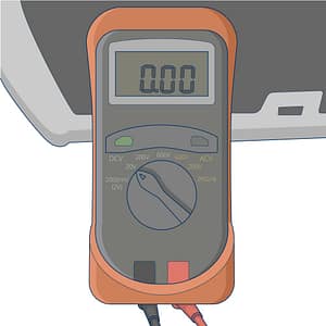
Turn the vehicle’s ignition OFF and the multi-meter should show 0 volts.
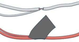
Strip back the vehicle’s constant and switch power wires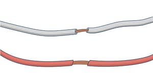
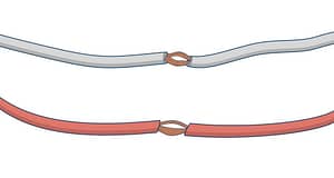
Spread the wires apart to create a small opening
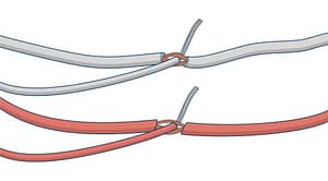
For models ST4215 and ST4310, insert the exposed end of the WHITE wire from the tracking device into the opening of the vehicle’s switched wire.
For models ST4340 and ST4345, insert the exposed end of the BLUE wire from the tracking device into the opening of the vehicle’s switched wire.
For all models, insert the exposed end of the RED wire from the tracking device into the vehicle’s constant wire.
Twist the tracking device’s wires around the vehicle’s wires.
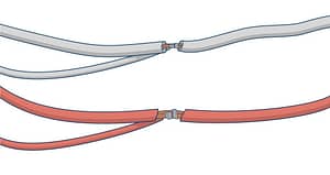
Wrap electrical tape around the exposed wires.
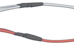
Secure the electrical tape with zip ties.

Connect a ring connector to the end of the black ground wire
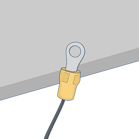
Use a self-tapping sheet metal screw to connect the ring connector to the vehicle’s chassis.

With the QR code sticker facing up, route the device under the dashboard toward a location in the upper portion of the dashboard (if possible)
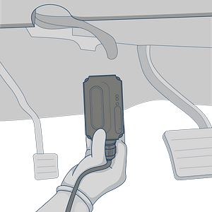
Find a secure location below the dashboard to mount the device. Use zip ties to secure it to a wiring bundle or to the vehicle’s frame to ensure that it does not slip out while the vehicle is in operation.
Required Information
Record the serial number for the device and the VIN/Year/Make/Model of the vehicle on your worksheet for activation.
Device Testing & Troubleshooting Guides
Select the device manufacturer displayed on the label.
Suntech