Suntech Plug & Play OBD-II Tracker Installation Guide

Installation Instructions for plug & play OBD-II Tracking Devices

Tools required: zip ties (provided in package)

Find the vehicle’s OBD-II port location. It is typically below the driver’s side of the dashboard or in the center console.
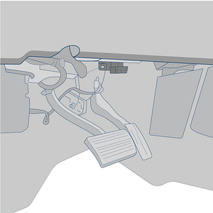
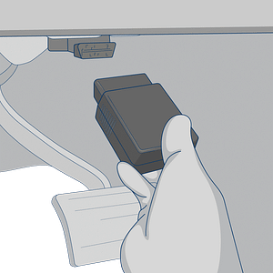
Plug the GPS tracker into the vehicle’s female OBD-II port.
Required Information

Record the serial number for the device and the VIN/Year/Make/Model of the vehicle on your worksheet for activation and email it to us at support@fieldlogix.com. The devices will update in the system as they begin driving after the activation process is complete.

Contact us at 888-803-0200 Option 2 if you encounter any issues with the installation


Testing & Troubleshooting the Suntech ST4500 Series Devices

In order to test the device, the vehicle must be parked outside in an open area so that it can receive a GPS lock. The device’s LEDs will indicate proper operation.

If you do not observe LED’s, please check the owner’s manual to determine which fuse provides power to the OBD-II port and verify that it isn’t bad.

An experienced technician can run a volt meter to the OBD-II port to verify that it is receiving 12 volts of power.  Find a ground source for the negative test connection and tap the positive end of the test connection to port 16 of the OBDII port.

OBDII port power pin 

Blue LED’s – Cellular Connectivity

plug & play tracker

The unit will power up as the vehicle’s ignition is turned on. The blue LED indicates cellular connectivity.  A normal operating device will blink once followed by a long pause. (there may be some brief flickers initially while the device initializes)

Blue LED errors will display the following blink patterns:

2 blinks and long pause

Issue: Can’t connect to server

Resolution: Reach out to support@fieldlogix.com

3 blinks and long pause

Issue: Can’t communicate with cell network

Resolution: Drive vehicle

4 blinks and long pause

Issue: Device may be defective

Resolution: Reach out to support@fieldlogix.com

6 blinks and long pause

Issue: Weak cellular connectivity

Resolution: Drive vehicle

7 blinks and long pause

Issue: SIM card is missing

Resolution: Open device & verify that SIM card is properly seated

Red LEDs – GPS Signal

gps tracker LED codes

The RED LED indicates GPS signal. Normal operation should display 1 red blink followed by a long pause.

Red LED errors will display the following blink patterns:

2 blinks and long pause

Issue: GPS reception is weak

Resolution: Move to an open outdoor area

4 blinks and long pause

Issue: Internal GPS not working

Resolution: Device may be defective. Reach out to support@fieldlogix.com

Contact support at 888-803-0200 Option 2 or support@fieldlogix.com if you encounter any issues with the installation or the troubleshooting steps do not resolve your issue

FieldLogix