Suntech Plug & Play OBD-II Tracker with J Harness Installation Guide

Installation Instructions for plug & play OBD-II Tracking Devices with the “J” Wiring Harness

Tools required: zip ties (provided in package)

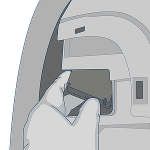
Find the vehicle’s OBD-II port location. It is typically below the driver’s side of the dashboard or in the center console.

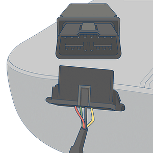
Plug the male OBD-II connector on the tracking device’s cable into the vehicle’s female OBD-II port.

Zip tie any excess wire to a wire loom behind the dashboard.

Plug the rectangular plug into the device.

connect OBDII unit to harness

With the QR code sticker facing up, route the device under the dashboard toward a location in the upper portion of the dashboard (if possible)

hide gps device

Find a secure location below the dashboard to mount the device. Use zip ties to secure it to a wiring bundle or to the vehicle’s frame to ensure that it does not slip out while the vehicle is in operation.

hide gps tracking device

Required Information

Record the serial number for the device and the VIN/Year/Make/Model of the vehicle on your worksheet for activation and email it to us at support@fieldlogix.com. The devices will update in the system as they begin driving after the activation process is complete.

Contact us at 888-803-0200 Option 2 if you encounter any issues with the installation


Testing & Troubleshooting the Suntech ST4500 Series Devices

In order to test the device, the vehicle must be parked outside in an open area so that it can receive a GPS lock. The device’s LEDs will indicate proper operation.

If you do not observe LED’s, please check the owner’s manual to determine which fuse provides power to the OBD-II port and verify that it isn’t bad.

An experienced technician can run a volt meter to the OBD-II port to verify that it is receiving 12 volts of power.  Find a ground source for the negative test connection and tap the positive end of the test connection to port 16 of the OBDII port.

OBDII port power pin 

Blue LED’s – Cellular Connectivity

plug & play tracker

The unit will power up as the vehicle’s ignition is turned on. The blue LED indicates cellular connectivity.  A normal operating device will blink once followed by a long pause. (there may be some brief flickers initially while the device initializes)

Blue LED errors will display the following blink patterns:

2 blinks and long pause

Issue: Can’t connect to server

Resolution: Reach out to support@fieldlogix.com

3 blinks and long pause

Issue: Can’t communicate with cell network

Resolution: Drive vehicle

4 blinks and long pause

Issue: Device may be defective

Resolution: Reach out to support@fieldlogix.com

6 blinks and long pause

Issue: Weak cellular connectivity

Resolution: Drive vehicle

7 blinks and long pause

Issue: SIM card is missing

Resolution: Open device & verify that SIM card is properly seated

Red LEDs – GPS Signal

gps tracker LED codes

The RED LED indicates GPS signal. Normal operation should display 1 red blink followed by a long pause.

Red LED errors will display the following blink patterns:

2 blinks and long pause

Issue: GPS reception is weak

Resolution: Move to an open outdoor area

4 blinks and long pause

Issue: Internal GPS not working

Resolution: Device may be defective. Reach out to support@fieldlogix.com

Contact support at 888-803-0200 Option 2 or support@fieldlogix.com if you encounter any issues with the installation or the troubleshooting steps do not resolve your issue

FieldLogix