Installation Guides
6 or 9 Pin “Y” Cable

Installation Instructions for the GenX5P and GenX6P Tracking Devices with the 6 pin or 9 pin “Y” Wiring Cable
Tools required: Phillips or Torx head screwdriver & zip ties (provided in package)
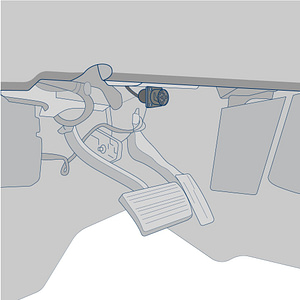
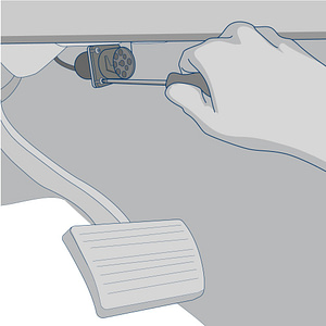
Find the vehicle’s 6 or 9 pin port location. It is typically below the driver’s side of the dashboard or in the center console.
Remove the vehicle’s existing 6 or 9pin connector from the plate with a phillips or Torx head screwdriver.
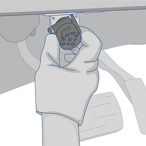
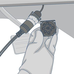
Remove the vehicle’s female 6 or 9 pin port from the plate.
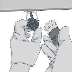
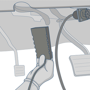
Plug the male adapter from the device’s harness into the vehicle’s female 6 or 9 pin plug.
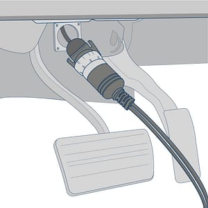
Secure the vehicle’s pre-existing 6 or 9 pin port below the dash with a zip tie. Take the female 6 or 9 pin plug from the device’s harness and insert into the plug from the tracking device.
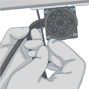
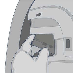
Use the male plug from the tracking device’s harness to replace the vehicle’s 6 or 9pin plug.
Use the screwdriver to mount the new plug onto the vehicle’s mounting plate.
Zip tie any excess wire to a wire loom behind the dashboard.
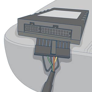
Plug the rectangular plug into the device.
Find a secure location below the dash board to mount the device. Use zip ties to secure it to a wiring bundle or to the vehicle’s frame to ensure that it does not slip out while the vehicle is in operation.
Mount the device with the identification labels faced upward to ensure the best satellite reception. The QR code sticker should be facing down.
Required Information
Record the serial number for the device and the VIN/Year/Make/Model of the vehicle on your worksheet for activation.
Testing & Troubleshooting the GenX Devices
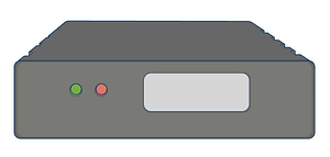
In order to test the device, the vehicle must be parked outside in an open area so that it can receive a GPS lock. use the LED code descriptions below to confirm proper operation or troubleshoot a malfunctioning device.
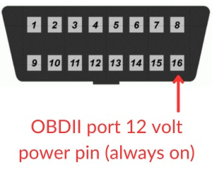
If you do not observe LED’s, please check the vehicle’s power source to the device for a bad fuse. If you are hard-wiring the device, verify that the ground connection is good. If you are plugging the device into the vehicle’s OBD-II port, check the owner’s manual to determine which fuse provides power to the port and verify that it isn’t bad.
An experienced technician can run a volt meter to the OBD-II port to verify that it is receiving 12 volts of power. Find a ground source for the negative test connection and tap the positive end of the test connection to port 16 of the OBDII port.
Green LED’s
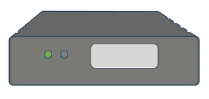
The unit will power up as the vehicle’s ignition is turned on. The Green LED will show solid for approximately 30 seconds (there may be some brief flickers initially while the device initializes). However, after initial startup, the LED should flash in the following sequence.
Ignition on: Rapidly blinks 25 times on and off every 10 seconds. Ignition off: Slow blinks 8 times on and off every 8 seconds. After several hours of being parked, it will blink once every 3 seconds.
A properly functioning device should have a flashing green LED and no red LED’s after it is fully booted.
Device Testing & Troubleshooting Guides
Select the device manufacturer displayed on the label.
GenX