Installation Guides
Hardwire Installation for Camera Only

Dash Camera Installation Guide
Instructions for the Surfsight Dash Camera Hardwire Installation
Tools required:
- Specialty screwdriver (provided in package)
- Electrical tape
- Small zip ties
- Phillips head screwdriver
- Trim removal tool or flat head screwdriver
- Small Phillips head self tapping sheet metal screw (#8 X 1/2″ length recommended)
- Wire crimper
- Digital multi-meter
Before starting, ensure that the vehicle is parked on an even level surface and that the windshield is dry and clean.
Connect to a Power Source
In order to ensure that the camera can detect motion events while the vehicle is powered off, the camera must be connected to a constant 12 volt power source.
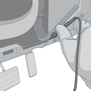
Use a flathead screwdriver or the trim removal tool to remove the panel from the lower portion of your driver’s side dashboard
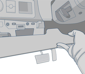
Once removed, set the panel aside to see the exposed portion underneath your dashboard.
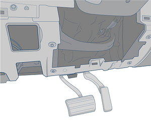
Locate the vehicle’s constant power wire in the steering column, at the fuse block, or Body Control Module.
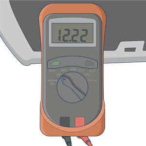
Setup your digital multi-meter and set to 20v in the DCV section.
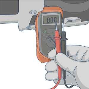
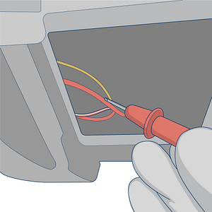
Connect the black ground wire from the multi-meter to a metal portion of the framing under the dashboard.
Locate the wire that you suspect would be the constant power wire. Probe the wire with the red multi-meter lead. Turn the vehicle’s ignition ON and OFF while the red meter lead is connected. If the meter shows 12 volts or more when the ignition is BOTH ON and OFF, then it is the constant wire.
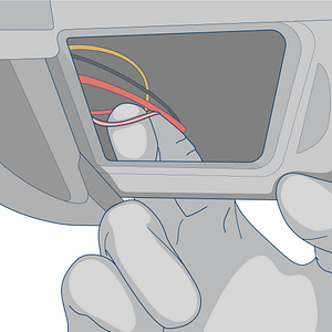
Strip back the vehicle’s constant power wire using your wire crimpers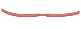
Spread the wires apart to create a small opening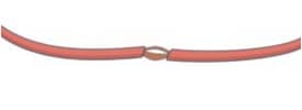
Insert the exposed end of the red wire from the camera into the vehicle’s constant wire.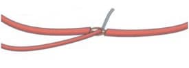
Twist the camera’s wires around the vehicle’s wires.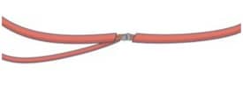
Wrap electrical tape around the exposed wires.
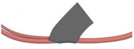
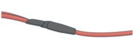
Secure the electrical tape with zip ties.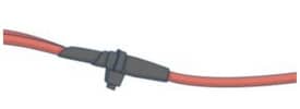
Connect a ring connector to the end of the ground wire
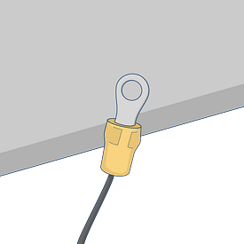
Use the self-tapping sheet metal screw to connect the ring connector to the vehicle’s chassis.
Be sure to find a bare-metal location for the ring connector.

Run the camera’s power cable through the vehicle’s “A” pillar (panel next to the windshield), tuck it into the headliner, and connect the plug to the device’s power jack

Mounting the Camera
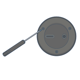
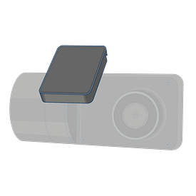
Unscrew the safety screws that lock the tamper proof case on the camera using the provided specialty screwdriver. This makes the mounting plate’s angle adjustable.
Do not remove the screws entirely
Place the camera as high as possible on the driver’s side of the windshield to establish the mounting position.
Be careful to avoid obstructing the driver’s view.
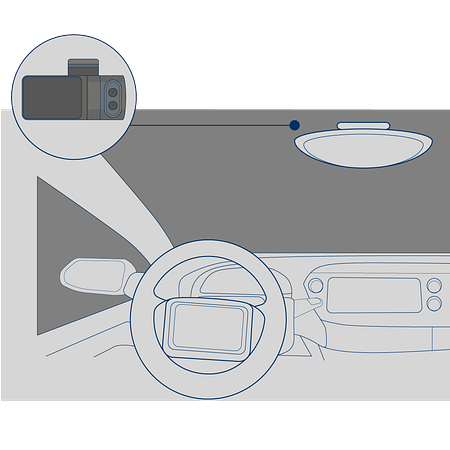
Use an alcohol wipe to clean the area in which the camera will be mounted. Remove the 3M adhesive tape cover from the mounting bracket and adhere the bracket to the dry windshield. Adjust the angle of the mounting plate to ensure that the camera is facing forward. Leave the safety screws loose.
Configuring the Camera Viewing Angle
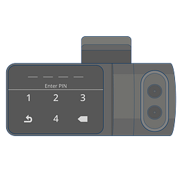
While mounted, unlock the camera touch screen by clicking on the screen and entering the code 3333.
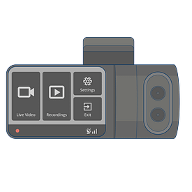
Click on “Live View” and adjust the angle of the camera to set the road facing camera and the cabin facing cameras to the proper angles.
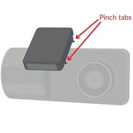
Remove the camera from the mounting bracket by pinching the tabs.
Tighten the security screws to lock the angle of the bracket.
Remount the camera into the mounting bracket on the windshield.

Calibrating the Camera
The camera contains an internal accelerometer that can be configured upon installation. Follow these instructions to calibrate your camera.
-
- Turn the vehicle’s ignition on
- Confirm that the camera’s power is on
- Press the touchscreen and enter the PIN 3333
- Click the “gear” icon to go to the settings menu
- Select calibrate
The calibration process will take approximately 5 seconds and must be repeated each time the camera is repositioned or placed in a different vehicle.
Once the installation is complete, contact us at support@fieldlogix.com to activate your camera. Please provide the VIN of the vehicle that the camera is being installed in as well as the IMEI and serial number for the camera.